|
[Tektronix] 5-IMDA 3-Phase Inverter Motor Drive Analysis
|
|
작성자 :
한국계측기
Date : 2020-03-31 15:29 | Hit : 18,552
|
| |
|
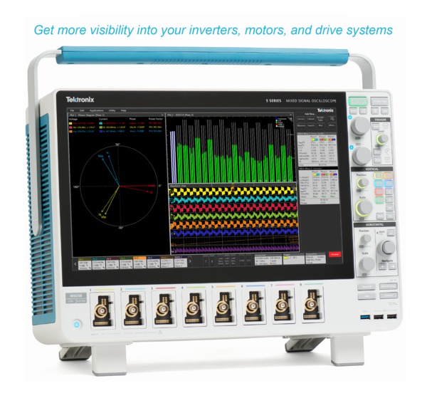
Measurements and analysis on three-phase power systems are inherently more complex than on single-phase systems. Although oscilloscopes can capture voltage and current waveforms with high sample rates, further calculations are required to produce key power measurements from the data. Power converters based on Pulse Width Modulation (PWM), such as variable-frequency motor drives, further complicate measurements since filtering and triggering on PWM signals are challenging. Yet for most validation and troubleshooting, understandably their oscilloscope is the instrument of choice for designers. Special software, designed to automate power analysis on inverters, motors, and drives, greatly simplifies important three-phase power measurements on PWM systems and can help engineers get faster insights into their designs. The Inverter Motor Drive Analysis (IMDA) solution from Tektronix helps engineers design better and more efficient three-phase motor drive systems, taking full advantage of the advanced user interface, six or eight analog input channels, and ‘High Res’ mode (16 bits) on the 5 Series MSO. The IMDA solution provides fast, accurate, and repeatable results for electrical measurements on industrial motors and drive systems for AC induction motors, permanent magnet synchronous motors (PMSM) and brushless DC (BLDC) motors.
Key features and specifications
Measurement overviewThree-phase power converters such as variable frequency drives require a range of measurements during the design process. The Inverters, Motors, and Drives Analysis package for the 5 Series MSO automates key electrical measurements which are grouped into three categories:
Each of these sections include key measurements which are critical to a motor design. Input analysisInput analysis includes the basic measurements used in most power equipment designs. The 5-IMDA solution automatically measures the current, voltage, and power values for different wiring configurations. The measurements can be set to measure 2V2I or 3V3I for 3P3W, and 3P4W to support various supply and motor configurations. Measurements can be performed line-to-line or line-to-neutral, to support delta or wye configurations. 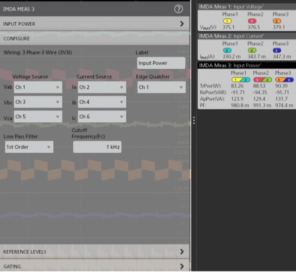 HarmonicsPower waveforms are rarely textbook sinusoids. Harmonics measurements break down non-sinusoidal voltage or current waveforms into their sinusoidal components, indicating the frequency and amplitude for each component. Harmonics analysis can be performed up the 200thharmonic. The maximum harmonic order can be set to suit your needs by specifying the range in the measurement configuration. THD-F, THD-R and fundamental values are measured for each phase. Measurements can be evaluated against the IEEE-519 standard, or custom limits. Test results can be recorded in a detailed report indicating pass/fail status. 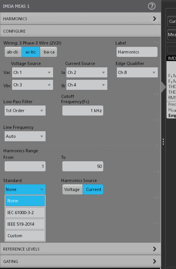 Power qualityThis group provides critical three-phase power measurements including: frequency and RMS magnitudes of voltage and current, crest factors of voltage and current, PWM frequency, true power, reactive power, apparent power, power factor, and phase angle for each phase. Voltage and current vectors can be displayed on a phasor diagram so you can quickly judge phase shift for each phase and the balance among phases. Each vector is represented by an RMS value and phase is computed using the DFT method. 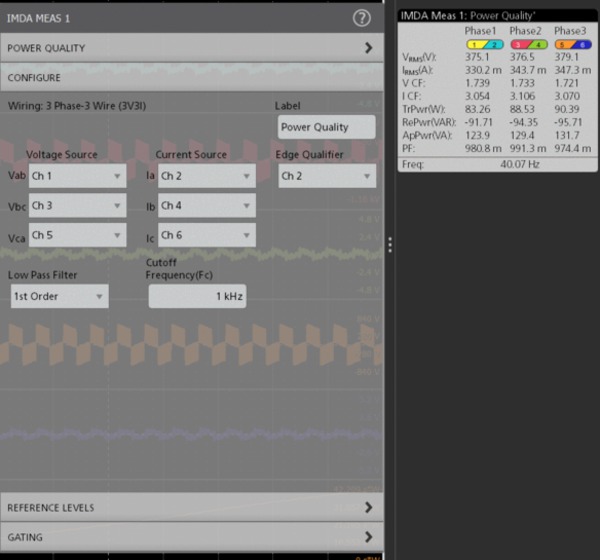 Output analysisThis group of measurements can help calculate the overall performance of the motor drive system. EfficiencyEfficiency measures the ratio of the output power to input power for respective input and output V and I pairs. By using the 2V2I method, three-phase efficiency may be measured using eight oscilloscope channels (2V2I on the input side and 2V2I on the output side). The solution calculates efficiency at each phase and the total (average) efficiency of the system. 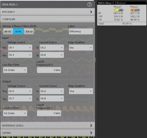 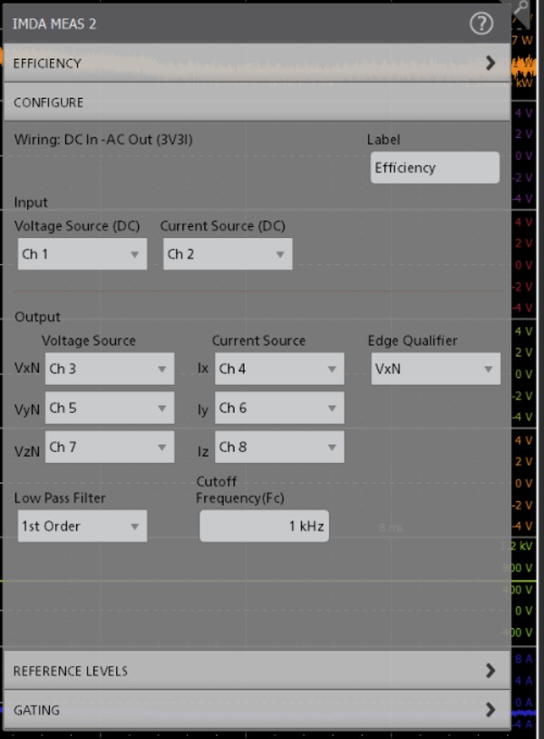 Phasor diagramThe measurement displays the magnitude and phase angle between Voltage(V) and Current(I) vectors in a phasor plot. The V and I vectors depend on the wiring configuration. 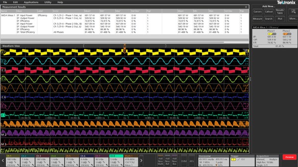 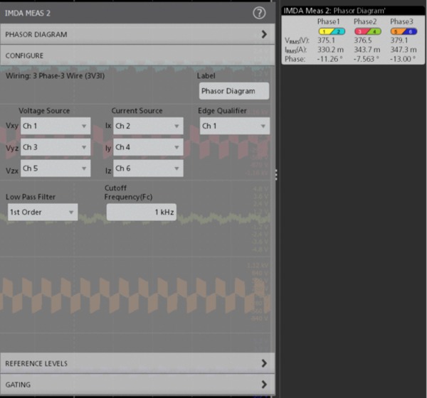 Ripple analysisRipple is defined as the residual AC voltage on a constant DC component (offset). Typically, the ripple component is often small in magnitude relative to the DC component. The solution measures two types of ripple:
Line ripple: The line ripple measures the RMS at the configured line ripple frequency and the peak-to-peak value of the time domain waveform for the configured phases. Switching ripple: The switching ripple measures the RMS at the configured switching ripple frequency and the peak to peak value of the time domain waveform for the configured phases. 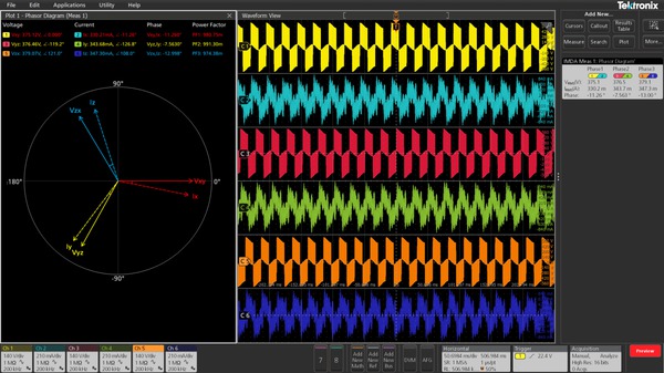 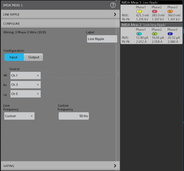 Report generationThe 5-IMDA software simplifies data collection, archiving, documentation of your design, and development process. It supports the report generation in MHT, PDF or CSV formats with pass/fail results for easy analysis. 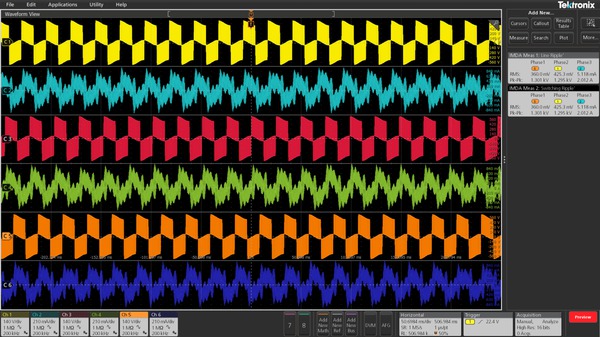
#텍트로닉스대리점 #5-IMDA #3상인버터모터드라이브분석 #BLDC모터분석
|
